EN
EN



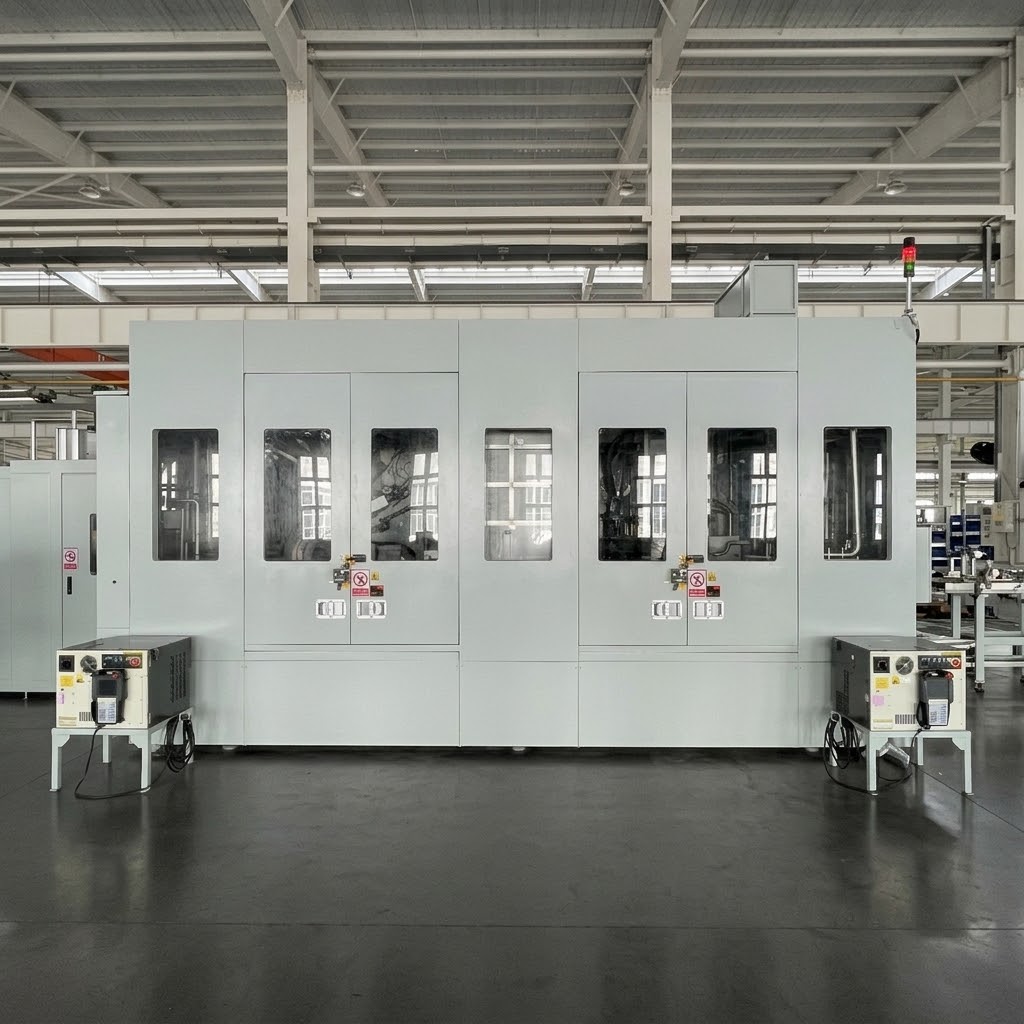
Automotive Cylinder Head Intermediate Cleaning System for Heavy-Duty Diesel Engine Manufacturing
Customized turnkey solution for a major heavy-duty diesel engine manufacturer
Application: Cylinder Head Intermediate Cleaning for Heavy-Duty Diesel Engine Manufacturing
Workpiece: Cylinder Head for Heavy-Duty Diesel Engines — Multiple Variants
Cleaning Process: Turbulent Cleaning (1.5 MPa) + Water Jacket Plug Cleaning (1.5 MPa) + Fixed-Point Cleaning (1.5 MPa) + Water Jacket Precision Cleaning (0.6 MPa) + Blow-Drying (0.2–0.4 MPa) + Vacuum Drying
Cleaning Pressure: Turbulent ≥1.5 MPa / Fixed-Point ≥1.5 MPa / Water Jacket Cleaning 1.5 MPa & 0.6 MPa — customizable
Cleaning Temperature: 40–60°C (Electric Heating) — customizable
Cycle Time: ≤38 seconds per piece (76s/2 pieces) — customizable per production line requirements
Cleanliness Requirement: Rocker Arm Oil Gallery ≤0.4 mg / Fuel Return Gallery ≤1.5 mg / Oil Return Gallery ≤7.3 mg / Intake & Exhaust Ports ≤14.5 mg / Cooling Jacket ≤56 mg — customizable per customer requirements
Drying Technology: Fixed-Point Blow-Drying (0.2–0.4 MPa) + Secondary Blow-Drying + Vacuum Drying
Filtration System: Three-Stage Filtration (50 μm / 30 μm / 10 μm) — customizable
Robot Configuration: 6-Axis Robots (IP67, 210 kg Payload, 2 Units) with Simultaneous Dual-Workpiece Handling — customizable
Loading/Unloading: Automatic Loading & Unloading
Description
Automotive Cylinder Head Intermediate Cleaning System
The Big Bird Industrial Cylinder Head Intermediate Cleaning System is developed for post-machining cleaning of cylinder heads used in heavy-duty diesel engine manufacturing. The system removes machining residues before subsequent processes and supports full automatic mixed-model production without manual changeover.
The equipment is provided as a turnkey solution including design, manufacturing, installation, and commissioning.
Workpiece Applications
The system accommodates multiple cylinder head variants for heavy-duty diesel engine manufacturing:
| Variant | Material | Weight |
|---|---|---|
| Variant A | Aluminum Alloy | 16.4 kg |
| Variant B | Aluminum Alloy | 16.6 kg |
| Variant C | Aluminum Alloy | 16.4 kg |
| Variant D | Aluminum Alloy | 15.8 kg |
| Variant E | Aluminum Alloy | 15.9 kg |
| Variant F | Aluminum Alloy | 15.8 kg |
All workpieces are cylinder head sub-assemblies for heavy-duty diesel engine applications. The system supports full automatic mixed-model production without manual changeover.
Automatic Mixed-Model Production
The system supports fully automatic mixed-model production with the following capabilities:
QR Code Recognition
QR code scanning devices automatically read workpiece identification upon loading. The system selects the appropriate cleaning program based on the QR code information. Storage capacity supports up to 256 part number variants. An additional automatic barcode printer (2 units) is configured for production traceability.
Dual-Workpiece Handling
The system features two 6-axis robots capable of handling two cylinder heads simultaneously, doubling production efficiency with a cycle time of 76 seconds per two pieces (38 seconds per piece).
Automatic Model Changeover
Fixtures, nozzles, and positioning components are designed to accommodate all cylinder head variants without manual intervention. Fixture locating surfaces feature automatic cleaning to prevent chip-induced workpiece damage.
MES Communication
The system interfaces with MES for production tracking, data acquisition, and status updates per the automotive OEM's general technical requirements.
Multi-Stage Cleaning Process
The system combines multiple cleaning technologies in a 9-stage automated sequence with dual-workpiece handling:
Stage 1: Loading (1ST)
The upstream conveyor transfers the workpiece to the cleaning system loading roller conveyor. The conveyor transports the workpiece to the machine入口. A QR code scanner (COGNEX) identifies the workpiece model.
The入口 features two workpiece positioning points. A lift-and-rotate mechanism lifts and rotates two workpieces 180°, enabling the robot to grip both cylinder heads simultaneously into the cleaning chamber. The loading conveyor features PZR roller design.
An operator inspection station is provided at the loading position.
Stage 2: Turbulent Cleaning (2ST) — 1.5 MPa
Robot #1 grips two workpieces and transfers them into the turbulent cleaning tank, which has been pre-filled with cleaning fluid. The robot flexibly changes workpiece orientation while surrounding nozzles direct turbulent flow to clean all surfaces.
Stage 3: Water Jacket Plug Cleaning (3ST) — 1.5 MPa
After turbulent cleaning, the tank drain valve opens for rapid drainage. The robot positions the workpieces at large-diameter nozzles for water jacket plug cleaning, ensuring thorough cleaning of cooling passages.
Stage 4: Fixed-Point Cleaning (4ST) — 1.5 MPa
After water jacket plug cleaning, the workpieces are positioned at fixed-point nozzle panels. Each nozzle is precisely aligned with corresponding holes on the cylinder head, ensuring all passages receive targeted cleaning. The robot changes workpiece orientation to align each surface with corresponding nozzle panels, and the cleaning pump continues refilling the turbulent tank for the next cycle.
Stage 5: Water Jacket Precision Cleaning (5ST) — 0.6 MPa
Robot #1 places two workpieces simultaneously onto the positioning pallets at this station. Cylinders extend nozzles to perform water jacket plug cleaning while simultaneously conducting precision cleaning of the overall workpiece. This station features two positions to extend precision cleaning time. Robot #1 places workpieces in one position while Robot #2 retrieves previously cleaned workpieces from the other position. This station features independent water tank, pump, and filtration system.
Stage 6: Fixed-Point Blow-Drying (6ST) — 0.2–0.4 MPa
Robot #2 grips the workpieces and moves them to the blow-drying station. During transfer, the robot changes workpiece orientation for tilt-drainage. The robot then positions the workpieces at fixed nozzle boxes for targeted blow-drying of all holes and passages. Each surface has corresponding nozzle panels. After fixed-point blow-drying, the robot performs scanning blow-drying across workpiece surfaces. After drying, Robot #2 places the workpieces onto the gravity roller conveyor at the machine outlet, and transfer bars simultaneously advance both workpieces to the next station.
Stage 7: Secondary Blow-Drying (7ST)
Transfer bars convey two workpieces into the secondary blow-drying chamber with gravity roller conveyor. Upper cylinders extend nozzle boxes for fixed-point scanning blow-drying of the overall workpiece. After secondary blow-drying, transfer bars simultaneously advance both workpieces to the next station.
Stage 8: Vacuum Drying (8ST)
Transfer bars convey two workpieces into the vacuum chamber with gravity roller conveyor. The upper movable hood closes with the bottom fixed hood to form a sealed chamber. The vacuum pump evacuates the chamber, lowering the saturated steam temperature to evaporate residual moisture from component surfaces. After vacuum drying, the vacuum chamber vents, the hood returns, and transfer bars advance both workpieces to the next station.
Stage 9: Unloading (9ST)
Transfer bars convey two workpieces to the unloading station gravity roller conveyor. Upon arrival, the gravity conveyor lowers, transferring workpieces to the motor-driven conveyor for individual transfer to downstream equipment. An operator inspection station is provided. The unloading conveyor features PZR roller design with workpiece presence detection.
Technical Cleanliness Control
For heavy-duty diesel engine manufacturing, cleanliness of internal passages directly affects engine reliability and performance.
The system is designed to meet strict cleanliness requirements for each cylinder head passage:
| Area | Cleanliness Limit | Particle Size | Pass Rate |
|---|---|---|---|
| Rocker Arm Oil Gallery | ≤0.4 mg | 0.36 mm | 100% |
| Fuel Return Gallery | ≤1.5 mg | ≤0.6 mm | 80% |
| Oil Return Gallery | ≤7.3 mg | ≤0.6 mm | 80% |
| Intake & Exhaust Ports | ≤14.5 mg | ≤0.6 mm | 80% |
| Cooling Jacket | ≤56 mg | 1.0 mm | 80% |
Advanced Filtration Management
The system employs a three-stage filtration system for the cleaning circuit and a two-stage filtration system for the precision cleaning circuit:
Cleaning Circuit Filtration (Three-Stage):
Stage 1: Drum filter — 1,500 L/min, 50 μm, stainless steel mesh, with auto-backflush and chip cart
Stage 2: Automatic back-flush filter — 30 μm, with back-flush magnetic separator
Stage 3: Bag filter — 900 L/min, 10 μm, non-woven fabric (1 standby + 1 active), with blockage alarm
Precision Cleaning Circuit Filtration (Two-Stage):
Stage 1: Basket filter — 300 L/min, 40 mesh, nylon mesh, with blockage alarm
Stage 2: Bag filter — 300 L/min, 10 μm, non-woven fabric (1 standby + 2 active), with blockage alarm
Filtration Features:
All filters feature blockage alarms displayed on HMI
Filter replacement does not affect normal equipment operation
Automatic separation of cleaning fluid from chips and waste residue
Mobile chip cart for easy disposal
Robot System
The system utilizes two FANUC robots for efficient dual-workpiece handling:
| Parameter | Specification |
|---|---|
| Robot Model | FANUC R-2000iC/210WE |
| Number | 2 units |
| Protection | IP67 (no raincoat required) |
| Reach | 2.45 m |
| Payload | 210 kg |
| Key Feature | Simultaneous dual-workpiece handling |
| Gripper | Corrosion-resistant pneumatic gripper with self-locking function (workpiece cannot fall on power/air loss) |
| Air Seal | Prevents moisture ingress, with pressure/flow monitoring and alarm |
Intelligent Manufacturing Integration
The system supports Industry 4.0 requirements through comprehensive data connectivity:
MES Communication
OPC UA protocol support
QR code-based workpiece tracking
Production status updates
Data Acquisition
Equipment fault monitoring (time, frequency)
Production count and cycle time recording
Equipment uptime tracking
Power consumption monitoring (SIEMENS smart meter)
Operator Interface
15" TFT color touch screen (minimum)
Chinese language interface
Workpiece information display
Cleaning program selection
Cleaning progress monitoring
Temperature and pressure display
Fault diagnosis and alarm display with troubleshooting guidance
Tank liquid level monitoring and alarm
Smart Features
Automatic lubrication at scheduled intervals
Automatic maintenance reminders on HMI
Remote diagnostic capability
Application Case
| Parameter | Specification |
|---|---|
| Project | Major Heavy-Duty Diesel Engine Manufacturer — Cylinder Head Intermediate Cleaning System |
| Workpiece | Multiple Cylinder Head Variants for Heavy-Duty Diesel Engines |
| Cycle Time | ≤38 seconds per piece (76s/2 pieces) |
| Production Capacity | ≥719 qualified pieces per 8-hour shift |
| OEE | ≥95% |
| Cleaning Technologies | Turbulent 1.5 MPa + Water Jacket Plug 1.5 MPa + Fixed-Point 1.5 MPa + Water Jacket Precision 0.6 MPa + Vacuum Drying |
| Cleaning Temperature | 40–60°C |
| Drying Method | Blow-Drying + Vacuum Drying |
| Filtration Accuracy | Three-Stage: 50 μm → 30 μm → 10 μm |
| Total Power | 165 kW (including 75 kW heaters) |
| Noise Level | ≤75 dB (under load) |
Complete Cleaning Solution
Big Bird Industrial provides comprehensive engineering solutions including:
Process Development
Component analysis for cylinder heads
Cleaning process design
Cleanliness requirement evaluation
Equipment Integration
Robotic cleaning systems with dual-workpiece handling
Turbulent cleaning technology
Water jacket plug cleaning systems
High-pressure fixed-point cleaning
Vacuum drying technology
Multi-stage filtration management
Automated material handling
Smart Manufacturing Connection
MES interface (OPC UA)
QR code traceability
Production data acquisition
Why Choose Big Bird Industrial
Heavy-Duty Engine Component Experience
Big Bird Industrial specializes in precision cleaning solutions for automotive powertrain components, with proven experience in cylinder head cleaning for heavy-duty diesel engine applications.
Dual-Workpiece Robotic Handling
The system features two FANUC robots capable of handling two cylinder heads simultaneously, delivering rapid cycle times of 38 seconds per piece with OEE ≥95% for high-volume production.
Multi-Stage Cleaning Technology
The system combines turbulent cleaning, water jacket plug cleaning, fixed-point cleaning, water jacket precision cleaning, blow-drying, and vacuum drying for comprehensive contaminant removal from complex cylinder head geometries.
System-Level Engineering Capability
The company provides complete solutions from cleaning process development to production integration, including robotic handling, high-pressure cleaning, vacuum drying, and MES connectivity.
Customized Non-Standard Engineering
Each component and production line has unique requirements. Big Bird Industrial provides customized engineering solutions based on:
Component structure and material analysis
Cleaning process development
Customized fixture and automation design
Factory layout and production flow integration
The company's non-standard engineering capability allows each cleaning system to be tailored to specific component geometry, cycle time requirements, cleanliness standards, and automation level.
Compliance with Standards
All equipment complies with ISO 13849, IEC 62061 (SIL3), GB 5226.1, and applicable Chinese and international safety standards. Pressure vessels are certified by third-party inspection authorities.
FAQ
What components does this cleaning system process?
This system is designed for cylinder head sub-assemblies for heavy-duty diesel engine models.
What contaminants can be removed?
It removes metal chips, machining particles, cutting fluid residues, and internal contamination from oil galleries, fuel passages, intake/exhaust ports, and cooling jackets.
Can it clean water jackets and oil galleries?
Yes. The system combines turbulent cleaning, water jacket plug cleaning, and fixed-point cleaning to reach all internal passages including rocker arm oil galleries, fuel return galleries, oil return galleries, intake/exhaust ports, and cooling water jackets.
What cleanliness levels can be achieved?
Rocker arm oil gallery ≤0.4 mg; fuel return gallery ≤1.5 mg; oil return gallery ≤7.3 mg; intake/exhaust ports ≤14.5 mg; cooling jacket ≤56 mg.
Does it support automated mixed-model production?
Yes. QR code recognition selects the appropriate cleaning program. Fixtures and nozzles are designed for all variants. No manual changeover is required.
What is the cycle time?
The system delivers ≤38 seconds per piece (76s/2 pieces), supporting production of ≥719 qualified pieces per 8-hour shift.
Does it support MES integration?
Yes. OPC UA communication, QR code traceability, production data acquisition, and MES interface are fully supported.
Cylinder Head Intermediate Cleaning
Cylinder Head Intermediate Cleaning in Heavy-Duty Diesel Engine Manufacturing
Cylinder head intermediate cleaning is a critical process between machining and subsequent operations in heavy-duty diesel engine manufacturing. The complex geometry of cylinder heads—including multiple oil galleries, fuel passages, intake/exhaust ports, and cooling water jackets—requires advanced cleaning technologies to remove machining residues, metal chips, and cutting fluid contaminants. Modern engine manufacturers demand strict cleanliness levels for internal passages to ensure reliable engine performance, fuel efficiency, and emissions compliance.
Turbulent Cleaning for Complex Cylinder Head Geometries
Turbulent cleaning provides superior contaminant removal for complex cylinder head geometries. By immersing the workpiece in heated cleaning fluid and creating turbulent flow, the technology reaches internal passages and blind holes that conventional spray cleaning cannot access. Combined with water jacket plug cleaning and fixed-point cleaning, turbulent cleaning ensures thorough removal of machining residues from all surfaces and internal passages.
Robotic Dual-Workpiece Handling for High-Volume Production
Robotic dual-workpiece handling systems enable high-volume production with rapid cycle times. Two robots handling two workpieces simultaneously achieve cycle times of 38 seconds per piece while maintaining consistent cleaning quality. Combined with QR code recognition and automatic model changeover, these systems support fully automatic mixed-model production without manual intervention.
Filtration Technology in Cylinder Head Cleaning
Effective filtration systems are fundamental to maintaining consistent cleaning quality in cylinder head cleaning. Three-stage filtration configurations—combining drum filters, automatic back-flush filters, and bag filters—enable continuous operation with non-stop filter changes. Filtration accuracy down to 10 μm ensures cleaning fluid quality is maintained, reducing recontamination risks and extending fluid life.
Technical Specifications
| Specification | Description |
|---|---|
| Product Type | Cylinder Head Intermediate Cleaning System |
| Application | Heavy-Duty Diesel Engine Cylinder Head Intermediate Cleaning |
| Workpiece | Multiple Cylinder Head Variants for Heavy-Duty Diesel Engines |
| Cleaning Technology | Turbulent (1.5 MPa) + Water Jacket Plug (1.5 MPa) + Fixed-Point (1.5 MPa) + Water Jacket Precision (0.6 MPa) + Vacuum Drying |
| Cleaning Temperature | 40–60°C (Electric Heating) |
| Drying Technology | Blow-Drying (0.2–0.4 MPa) + Secondary Blow-Drying + Vacuum Drying |
| Cycle Time | ≤38 seconds per piece (76s/2 pieces) — customizable |
| Production Capacity | ≥719 qualified pieces / 8-hour shift |
| OEE | ≥95% |
| Robot Model | FANUC R-2000iC/210WE (2 units) |
| Robot Protection | IP67 |
| Robot Reach | 2.45 m |
| Robot Payload | 210 kg |
| Filtration System | Three-Stage: 50 μm → 30 μm → 10 μm |
| Control System | SIEMENS S7-1500 PLC |
| Communication Protocol | PROFINET, OPC UA |
| Loading/Unloading | Automatic |
| Power Supply | AC 380V 50Hz Three-Phase |
| Total Power | 165 kW (including 75 kW heaters) |
| Compressed Air | 8 Nm³/min |
| Water Consumption | 4,000 L (Total Tank Capacity) |
| Noise Level | ≤75 dB (under load) |
| Footprint | 11,000 × 6,070 mm |
| Safety Standards | GB/T 15706, IEC 62061 (SIL3), GB 5226.1 |